- 您现在的位置:买卖IC网 > Sheet目录341 > MAX8831EWE+T (Maxim Integrated)IC LED DRIVR WHITE BCKLGT 16-WLP
�� �
�
�High-Efficiency,� White� LED� Step-Up� Converter�
�with� I� 2� C� Interface� in� 2mm� x� 2mm� WLP�
�The� other� three� regulators� (LED3,� LED4,� LED5)� are� suit-�
�able� for� keyboard� backlight� functions� or� for� driving� sig-�
�nal� indicators,� and� are� programmable� up� to� 5.0mA�
�using� a� 32-step� logarithmic� dimming� scheme.� The� low-�
�current� regulators� (LED3,� LED4,� LED5)� can� be� operat-�
�ed� from� the� step-up� converter� or� from� a� separate� low-�
�voltage� source.�
�The� I� 2� C� interface� controls� all� operational� aspects� of� the�
�current� regulators,� including:� on/off� state,� LED� current,�
�ramp-up/ramp-down� timers,� and� blink� rate� timers�
�(LED3,� LED4,� LED5).� The� MAX8831� I� 2� C� write/read�
�addresses� are� factory� set� at� 0x9A/0x9B� (contact� the�
�factory� for� other� address� options).�
�25�
�20�
�15�
�10�
�5�
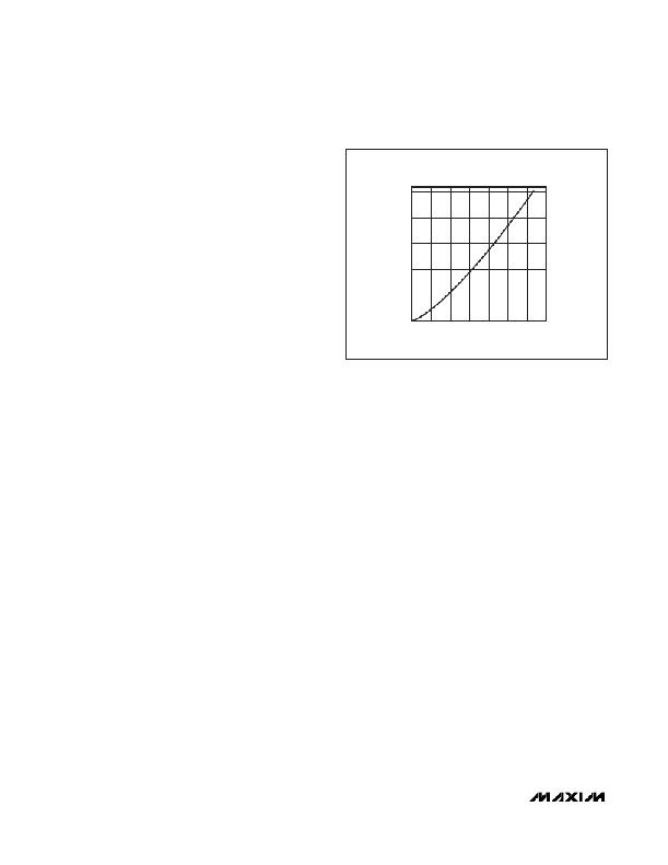
�LED1,� LED2� CURRENT� vs.� ILED1,�
�ILED2� CONTROL� REGISTER� VALUE�
�The� IC� features� several� protective� features,� including:�
�open/short� LED� fault� detection,� output� overvoltage� pro-�
�0�
�0�
�20�
�40�
�60�
�80�
�100�
�120�
�140�
�tection,� thermal� shutdown,� and� open� Schottky� diode�
�detection.� The� status� of� each� fault� is� monitored� continu-�
�ally� for� readback� through� the� I� 2� C� interface.�
�Fixed-Frequency� Step-Up� Controller�
�The� MAX8831’s� fixed-frequency,� current-mode,� step-up�
�controller� automatically� chooses� the� lowest� active� LED_�
�voltage� to� complete� the� feedback� loop� (Figure� 1).�
�Specifically,� the� difference� between� the� lowest� LED_�
�voltage� and� the� 350mV� reference� is� integrated� by� the�
�error� amplifier.� The� resulting� error� signal� is� compared� to�
�the� external� switch� current� plus� slope� compensation� to�
�terminate� the� switch� on-time.� As� the� load� changes,� the�
�error� amplifier� sources� or� sinks� current� to� COMP� to�
�adjust� the� required� peak� inductor� current.� The� slope-�
�compensation� signal� is� added� to� the� current-sense� sig-�
�nal� to� improve� stability� at� high� duty� cycles.�
�At� light� loads,� the� MAX8831� automatically� skips� pulses�
�to� improve� efficiency� and� to� prevent� overcharging� the�
�output� capacitor.� In� SKIP� mode,� the� inductor� current�
�ramps� up� for� a� minimum� on-time� of� 20ns� (typ),� then� dis-�
�charges� the� stored� energy� to� the� output.� The� switch�
�remains� off� until� another� pulse� is� needed� to� step-up� the�
�output� voltage.�
�When� the� MAX8831� is� programmed� by� the� I� 2� C� interface�
�to� use� an� alternate� supply� voltage� for� the� LED3,� LED4,�
�or� LED5� string� (see� the� Low-Current� Regulators� (LED3,�
�LED4,� LED5)� section),� internal� logic� masks� that� LED_�
�input� and� it� is� not� used� to� regulate� the� step-up� convert-�
�er� output.�
�High-Current� Regulators� (LED1,� LED2)�
�The� MAX8831� contains� two� low-dropout� (200mV� max),�
�25.25mA� linear� current� regulators� (LED1,� LED2)� that�
�can� each� drive� up� to� 9� series� LEDs� (depending� on� LED�
�string� forward� voltage)� for� display� backlighting� func-�
�ILED1,� ILED2� CONTROL� REGISTER� VALUE� (INTEGER)�
�Figure� 2.� LED1,� LED2� String� Current� vs.� I� LED1� ,� I� LED2� Control�
�Register� Value�
�tions.� Each� high-current� regulator� is� independently�
�enabled� and� is� programmable� from� 50μA� to� 25.25mA� in�
�128� logarithmic� steps� (Table� 1,� Figure� 2)� using� the� I� 2� C�
�interface.� Additionally,� the� I� 2� C� interface� programs� the�
�ramp-up� and� ramp-down� timers� for� each� regulator� to�
�one� of� eight� different� timing� settings.� See� the� MAX8831�
�I� 2� C� Registers� section� for� details� on� I� 2� C� control� of� the�
�high-current� regulators.�
�Low-Current� Regulators�
�(LED3,� LED4,� LED5)�
�The� MAX8831� also� contains� three� low-dropout� (150mV�
�max),� 5.0mA� linear� current� regulators� (LED3,� LED4,�
�LED5)� that� can� each� drive� up� to� 9� series� LEDs� for� key-�
�pad� backlighting� or� signal� indicator� functions.� Each�
�current� regulator� is� independently� enabled,� and� is� pro-�
�grammable� from� 50μA� to� 5.0mA� in� 32� logarithmic� steps�
�(Table� 2,� Figure� 3)� using� the� I� 2� C� interface.� Individual�
�ramp-up� and� ramp-down� timers� are� programmable� for�
�LED3,� LED4,� and� LED5,� with� eight� possible� timing� set-�
�tings.� The� individual� blink� ON� and� blink� OFF� timers� for�
�each� low-current� regulator� are� also� programmable,� or�
�these� features� can� be� disabled.� See� the� MAX8831� I� 2� C�
�Registers� section� for� details.�
�The� LED3,� LED4,� and� LED5� low-current� regulators� can�
�be� powered� from� an� alternate� external� source.� By� pro-�
�gramming� the� BOOST_CNTL� register,� internal� logic�
�masks� that� LED_� input� and� it� is� not� used� to� regulate� the�
�step-up� converter� output.�
�10�
�______________________________________________________________________________________�
�发布紧急采购,3分钟左右您将得到回复。
相关PDF资料
MAX8834ZEWP+T
IC LED DRIVR BCKLGT FLASH 20-WLP
MAX8855EVKIT+
KIT EVAL FOR MAX8855
MAX8879ETG+T
IC LED DRVR WT/RGB BCKLGT 24TQFN
MAX8901BETA+TCH8
IC LED DRIVER WHITE BCKLGT 8TDFN
MAX8930EWJ+T
IC LED DRVR WT/RGB BCKLGT 49WLP
MAXQ2000-KIT
EVAL KIT FOR MAXQ2000
MAXQ610-KIT#
EVALUATION KIT FOR MAXQ610
MB2146-401-01A
KIT STARTER F2MC-8FX 3V
相关代理商/技术参数
MAX8833ETJ+
功能描述:直流/直流开关调节器 Dual 3A 2MHz Step-Down Regulator RoHS:否 制造商:International Rectifier 最大输入电压:21 V 开关频率:1.5 MHz 输出电压:0.5 V to 0.86 V 输出电流:4 A 输出端数量: 最大工作温度: 安装风格:SMD/SMT 封装 / 箱体:PQFN 4 x 5
MAX8833ETJ+T
功能描述:直流/直流开关调节器 Dual 3A 2MHz Step-Down Regulator RoHS:否 制造商:International Rectifier 最大输入电压:21 V 开关频率:1.5 MHz 输出电压:0.5 V to 0.86 V 输出电流:4 A 输出端数量: 最大工作温度: 安装风格:SMD/SMT 封装 / 箱体:PQFN 4 x 5
MAX8834YEVKIT+
功能描述:LED 照明开发工具 Adaptive Step-Up Converters with 1.5A Flash Driver RoHS:否 制造商:Fairchild Semiconductor 产品:Evaluation Kits 用于:FL7732 核心: 电源电压:120V 系列: 封装:
MAX8834YEWP+T
功能描述:LED照明驱动器 Adaptive Step-Up Converter RoHS:否 制造商:STMicroelectronics 输入电压:11.5 V to 23 V 工作频率: 最大电源电流:1.7 mA 输出电流: 最大工作温度: 安装风格:SMD/SMT 封装 / 箱体:SO-16N
MAX8834ZEWP+T
功能描述:LED照明驱动器 Adaptive Step-Up Converter RoHS:否 制造商:STMicroelectronics 输入电压:11.5 V to 23 V 工作频率: 最大电源电流:1.7 mA 输出电流: 最大工作温度: 安装风格:SMD/SMT 封装 / 箱体:SO-16N
MAX8836ZEREEE+T
功能描述:电流型 PWM 控制器 1.2A PWM Step-Down Converter RoHS:否 制造商:Texas Instruments 开关频率:27 KHz 上升时间: 下降时间: 工作电源电压:6 V to 15 V 工作电源电流:1.5 mA 输出端数量:1 最大工作温度:+ 105 C 安装风格:SMD/SMT 封装 / 箱体:TSSOP-14
MAX8836ZEWEEE+
制造商:Rochester Electronics LLC 功能描述: 制造商:Maxim Integrated Products 功能描述:
MAX8836ZEWEEE+T
制造商:Maxim Integrated Products 功能描述: